Chapter 9 I/0
约 1190 个字 11 张图片 预计阅读时间 4 分钟
Abstract
Covered in Lecture 8, 2022.7.19 and Lecture 9, 2022.7.20
Topics:
1. Input & Output
2. Trap
3. Interrupt
Privilege, Priority and the Memory Address Space
Privilege and Priority
- Privilege: the right to do something. It contains Supervisor mode and User mode.
- Priority: the urgency of a program to execute.
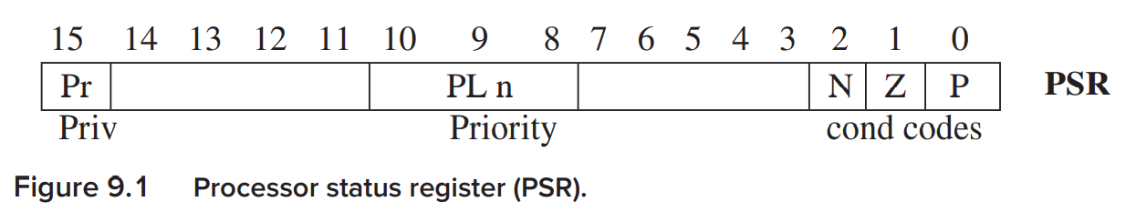
PSR(Process Status Register)
-
bit[15] is the privilege bit(0 for having privilege, 1 for not)
-
bit[10:8] is the priority. priority level 0-7(PL0 ~PL7). The PL of a program is always the same as the PL of the request to run the program.
Organization of Memory
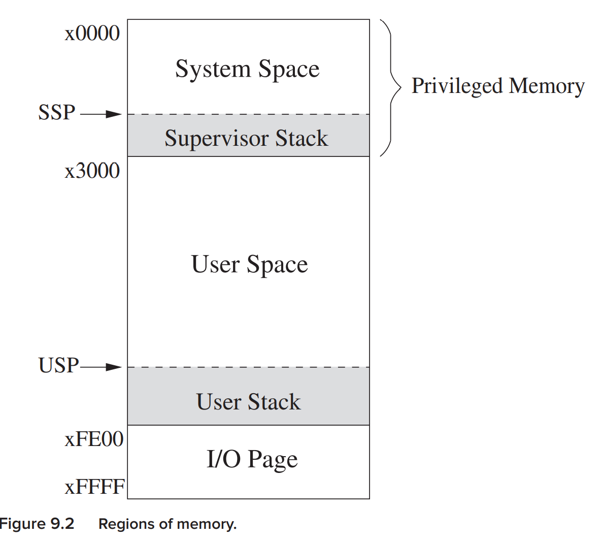
Addresses xFE00 to xFFFF do not correspond to memory locations at all. Addresses xFE00 to xFFFF are used to identify registers that take part in input and output functions and some special registers associated with the processor.
Address space != Memory location
In LC-3, our address space is \(2^{16}\) while not all addresses are for memory. xFE00-xFFFF actually doesn't belong to memory location.
Each stack has a stack pointer, SSP(Supervisor Stack Pointer) and USP(User Stack Pointer), and only one of the 2 stacks is active at any one time. R6 is generally used as SP for the active stack, and we have 2 registers Saved_SSP and Saved_USP to save the SP not in use. e.g. When from Supervisor mode to User mode, SP is stored in Saved_SSP and is loaded from Saved_USP.
Input/Output
Some Basic Characteristics of I/O
All I/O activity is controlled by instructions in the computer’s ISA.
- Does the ISA need special instructions for dealing with I/O?
- Does the I/O device execute at the same speed as the computer, and if not, what manages the difference in speeds?
- Is the transfer of information between the computer and the I/O device initiated by a program executing in the computer, or is it initiated by the I/O device?
Memory-Mapped I/O vs. Special I/O Instructions
Some computers use special input and output instructions while most computers prefer to use the same data movement instructions that are used to move data in and out of memory.
Memory-Mapped I/O: the I/O device registers are mapped to a set of addresses that are allocated to I/O device registerds.
Address xFE00 to xFFFF are reserved for I/O device registers.
Note
By memory-mapped I/O, we can regard the device registers as the memory locations so we can use the same instructions.
Asynchronous vs. Synchronous
I/O devices usually operate at speeds very different from that of a microprocessor, and not in lockstep. We call this latter characteristic asynchronous. Need protocol or handshaking mechanism. => Synchronization A single flag, called the ready bit, is enough to synchronize. When the ready bit is 1, it means we need to read a value or write a value.
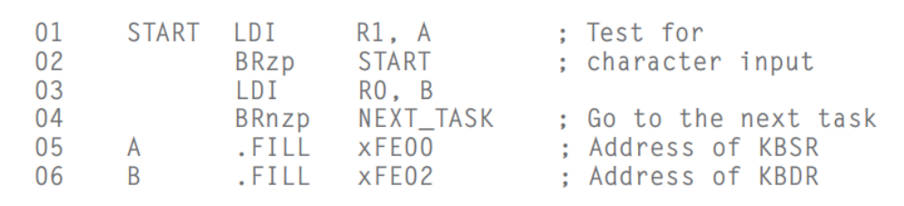
Interrupt-Driven vs. Polling
Interrupt-Driven I/O is that the keyboard controls the interaction. The processor does it own thing untill being interrupted by an announcement from the keyboard. Polling is that that the processor controls the interaction. The processor interrogates the ready bit untill it detects it's set.
Input from the Keyboard
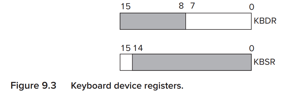
- KBSR(KeyBoard Status Register)
- address xFE00 is assgned to KBSR.
-
bit[15] is the ready bit.
-
KBDR(KeyBoard Data Register)
- address xFE02 is assgned to KBDR.
- bit[7:0] are used for the data, bit[15:8] contain x00.
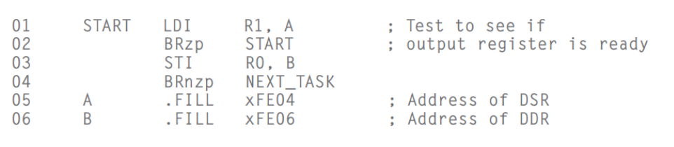
Output to the Monitor
The figure is almost the same as Figure 9.3
- DSR(Display Status Register)
- address xFE04 is assgned to DSR.
-
bit[15] is the ready bit.
-
DDR(Display Data Register)
- address xFE06 is assgned to DDR.
- bit[7:0] are used for the data, bit[15:8] contain x00
Datapath:

Operating System Service Routines(LC-3 Trap Routines)
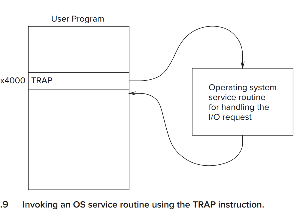
The Trap Mechanism
-
A set of service routines
-
A table of the starting addresses: Trap Vector Table is stored in memory locations x0000 to x00FF. What is stored here is the starting address of trap.
-
The TRAP instruction
-
A linkage back to the user program
The TRAP Instruction
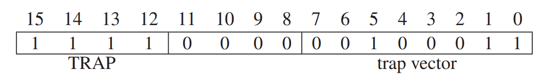
Its opcode is 1111, bit[11:8] must be 0, and bit[7:0] is the trap vector. During the EXECUTE phase we do 3 things:
- PSR and PC are both pushed onto the system stack.cThe return linkage is automatically save in the PC(+1).
- PSR[15] will be set to 0 and [10:8] remains unchanged. Note that the trap service doesn't need the privilege.(but when executing we should be Super) So if we are User Mode, we will turn to Super Mode. Save R6 in Saved_USP and load R6 from Saved_SSP.
- The 8-bit trap-vector is zero-extended to 16 bits to form an address that correspounds to a location in the Trap Vector Table.
The RTI Instruction
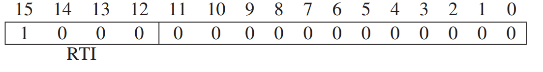 RTI(Return from Trap or Interrupt)
Its opcode is 1000, with no operands, bits[11:0] must be zero.
It pops the top two values on the system stack into the PC and the PSR. Then PSR[15] is restored.
RTI(Return from Trap or Interrupt)
Its opcode is 1000, with no operands, bits[11:0] must be zero.
It pops the top two values on the system stack into the PC and the PSR. Then PSR[15] is restored.
Interrupt
Is the transfer of information between the computer and the I/O device initiated by a program executing in the computer, or is it initiated by the I/O device?
- computer: polling
- I/O device: interrupt
What Is Interrupt-Driven I/O?
The I/O device can:
- force the running program to stop,
- have the processor execute a program that carries out the needs of the I/O device,
- have the stopped program resume execution as if nothing had happened.
Since polling requires the processor to waste a lot of time, we have interrupt-driven I/O.
How to achieve Interrupt-Driven I/O?
There are 2 parts to interrupt-driven I/O:
- the mechanism that enables an I/O devices to interrupt the processor
- the mechanism that handles the interrupt request
PartⅠ: Causing the Interrupt to Occur
- The I/O device must want service.
The ready bit of the KBSR or the DSR is set to be 1. - The device must have the right to request the service.
In most I/O devices, the interrupt enable(IE) bit is part of the DSR/KDSR.(IE bit:bit[14])
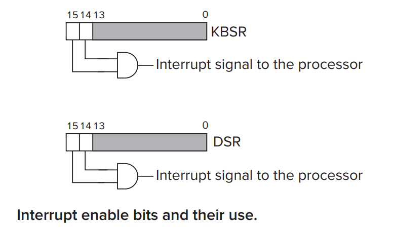 The interrupt request signal from the I/O device is the logical AND of the IE bit and the ready bit.
- The device must be more urgent than what the processor is currently doing.
To interrupt the running program, the device must have a higher priority than the program that is currently running.
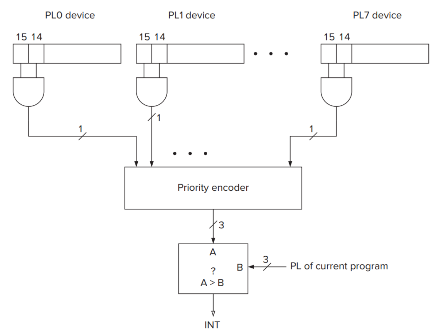 If the INT signal is asserted, we can trigger our interrupt.
!!! Note Although interrupts can happen at any time, but we assume the interrupt only happens between the instruction. It will not interrupt the instruction executing. So when INT signal is asserted, we will test whether we can enable the processor to stop.
PartⅡ: Handling the Interrupt Request
- Initiate the interrupt
- Save the state of the interrupted program PC, PSR, USP, GPR, memory locations. (in LC-3, only PC and PSR are stored in the stack and USP is stored by Save_USP) (push PSR first then push PC)
- Load the state of the interrupt rouinte
- Most processors use the mechanism of vectored interrupts interrupt vector provided by the device -> choose -> INTV; Interrupt Vector Table at x0100 to x01FF
- Service the interrupt
- Return from the interrupt
by
RTI(pop PC and PSR, and may adjust SP)
Not Just I/O Devices
不只有 I/O 会带来中断 . 中断向量表中 0100~0