Chapter 5 LC-3
约 829 个字 19 张图片 预计阅读时间 3 分钟
Abstract
Covered in Lecture 4, 2022.7.14 and Lecture 5, 2022.7.15
Topics:
1. ISA of LC-3.
2. Microarchitecture of LC-3.
ISA
Memory Organization
- address space: \(2^{16}\)(i.e.65536) locations.
Not all 65536 addresses are actually used for memory locations. - addressability: 16 bits. It's also called word-addressable.
Registers
Each register is called a GPR(General Purpose Register). They are referred to as R0, R1, ... R7.
Instruction Set
An instruction is made up of two things, opcode and oprands.
The instruction set is defined by its set of opcdeos, data types and addressing modes.
- opcode: 3 different kinds. Operates, data movement and control.
Data Types
Every opcode will interpret the bit patterns of its operands according to the data type it's designed to support.
Addressing Modes
Addressing mode is a mechanism for specifying where the operand is located.
5 modes in LC-3: immediate(or literal), register and 3 memory addressing modes: PC-relative, indirect and Base+offset.
Operate Instructions
Operation instructions process data.
ADD, AND and NOT
-
NOT
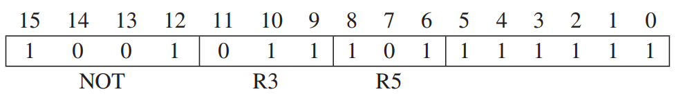 Its opcode is 1001, and bits[11:9] is DR, bits[8:6] is SR, and bits[5:0] are set to 1.
its datapath:
Its opcode is 1001, and bits[11:9] is DR, bits[8:6] is SR, and bits[5:0] are set to 1.
its datapath:

-
ADD Note that no all 2's complement intergers can be immediate operands. its datapath:

注 : AND 与 ADD 的 datapath 相同
实现 SUB
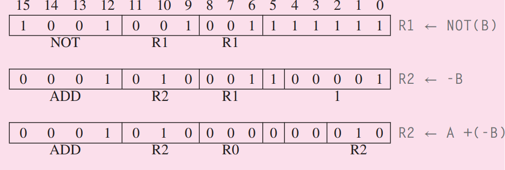
`A - B = A + (-B)' 所以我们将 B 按位取反再加一 .
LEA
LEA(opcode=1110) loads the register specified by bits[11:9] of the instruction with the value formed by adding the incremented PC to the sign-extended bits[8:0] of the instruction.
LEA is useful to initiallize a register with an address.
Note that the values to be loaded into the register does not involve any access to memory.

Note that LEA does not effect on CC.
Data Movement Instructions
Data movement instructions between GPR and memory or between registers and input/output devices.
The LC-3 contains 6 instructions that move formation: LD, LDR, LDI, ST, STR, STI.
The format:
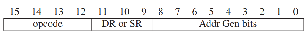
- bits[8:0]: address generation bits.
PC-Relative Mode
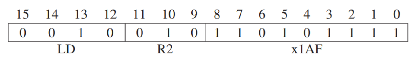 LD(opcode=0010) and ST(opcode=0011) specify the PC-relative addressing mode.
The memory address is computed by signed-extending bits[8:0] to 16 bits and adding the result to the incremented PC(incremented during FETCH phase).
Note that CC will be set depending on whether the value loaded or stored.
Note that the address of the memory opearand is limited to a small range.(\([-255, +256]\))
LD(opcode=0010) and ST(opcode=0011) specify the PC-relative addressing mode.
The memory address is computed by signed-extending bits[8:0] to 16 bits and adding the result to the incremented PC(incremented during FETCH phase).
Note that CC will be set depending on whether the value loaded or stored.
Note that the address of the memory opearand is limited to a small range.(\([-255, +256]\))

Indirect Mode
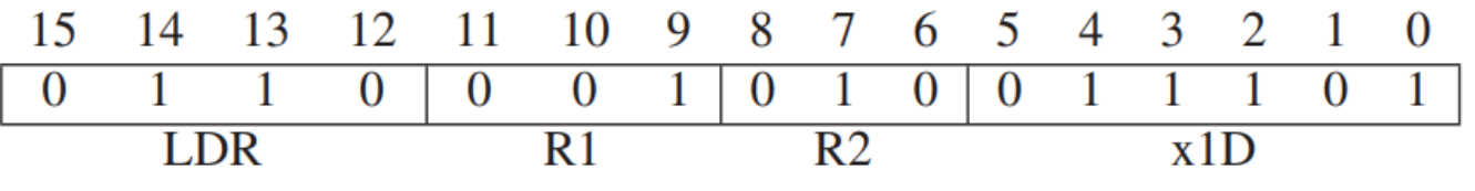
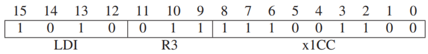 LDI(opcode=1010) and STI(opcode=1011) specify the indirect addressing mode.
An address is first formed exactly the same way as with LD, however, the result is the address of the address of the operand. So we need to interrogate memory first to obtain the address of the operand(like LD).
Note that the address of the operand can be anywhere.
Base+offset Mode
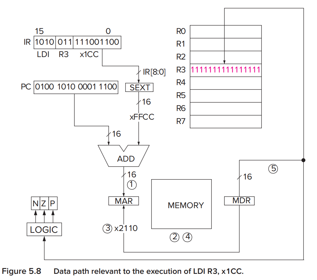
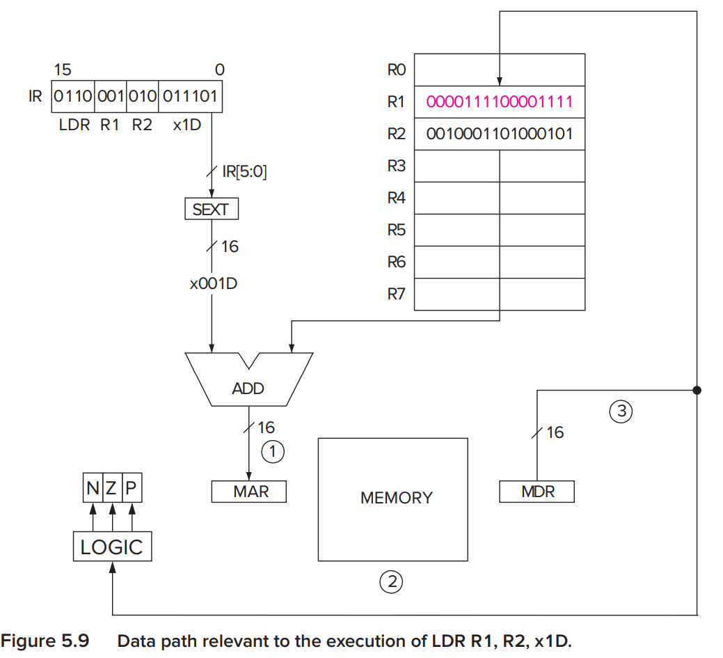
LDR(opcode=0110) and STR(opcode=0111) specify the Base+offset addressing mode.
The address is obtained by adding a signed-extended 6-bit(bits[5:0]) offset to a base register(bits[8:6]).
Note that the address of the operand can also be anywhere.
Control Instructions
The LC-3 has 5 opcodes that enable the sequential execution flow to be broken: conditional branch, unconditional jump, subroutine call(funtion), TRAP(service call) and RTI.
Conditional Branches
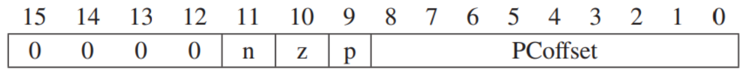
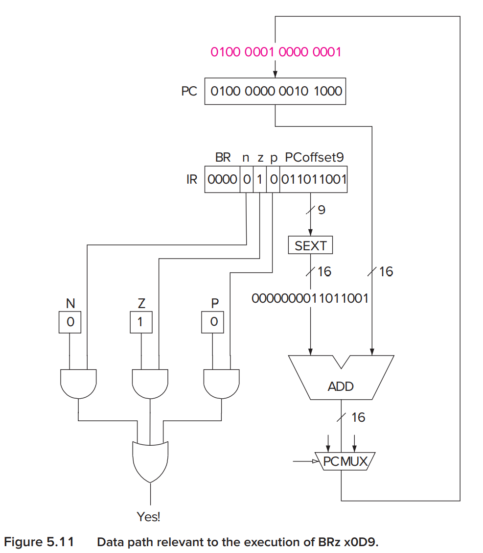
Note that if all bits[11:9] are 1, then it equals an unconditional branch. If all bits[11:9] are 0, then it equals nop.
Two methods of Loop Control
-
loop control with a counter

-
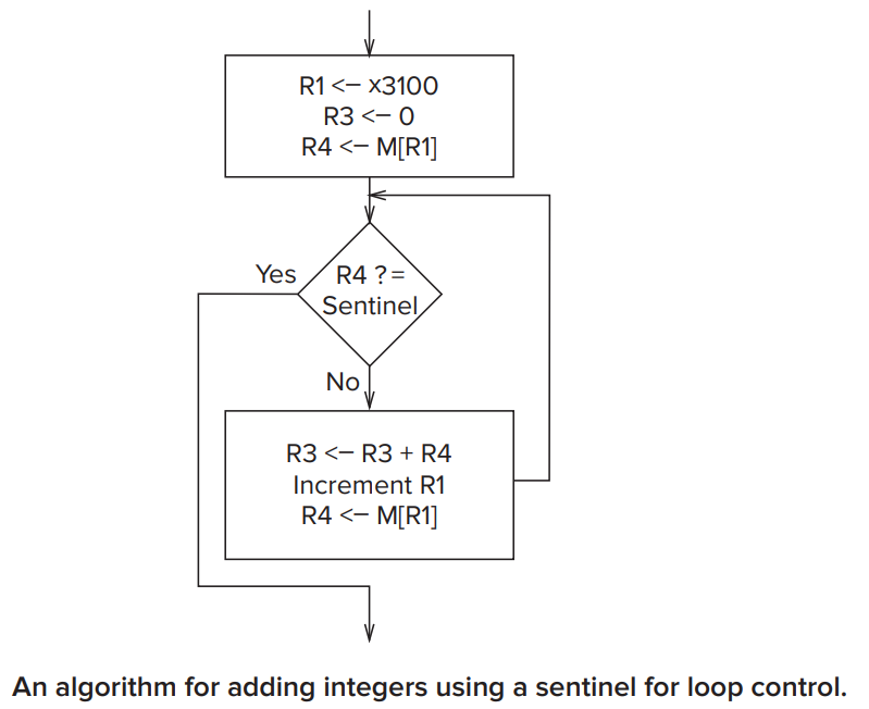
loop control with a sentinel
If we don't know ahead of time how many iterations we will want to perform.
JMP
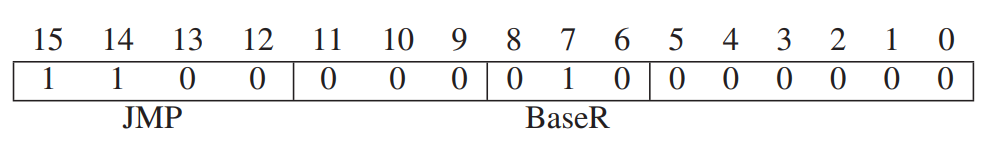
The JMP instruction(opcode=1100) loads the PC with the contents of the register specified by bits[8:6] of the instruction. (its addressing mode is by register)
TRAP
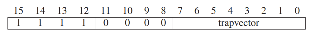
The TRAP instruction(opcode=1111) changes the PC to a memory address that is part of the operating system so that the OS will perform some task on behalf of the program. Once the service call ends, the PC is set to be the address of the instruction following the TRAP instruction.
- Input a character from the keyboard(trapvector = x23)
- Output a character to the monitor(trapvector = x21)
- Halt the program(trapvector = x25)
Datapath
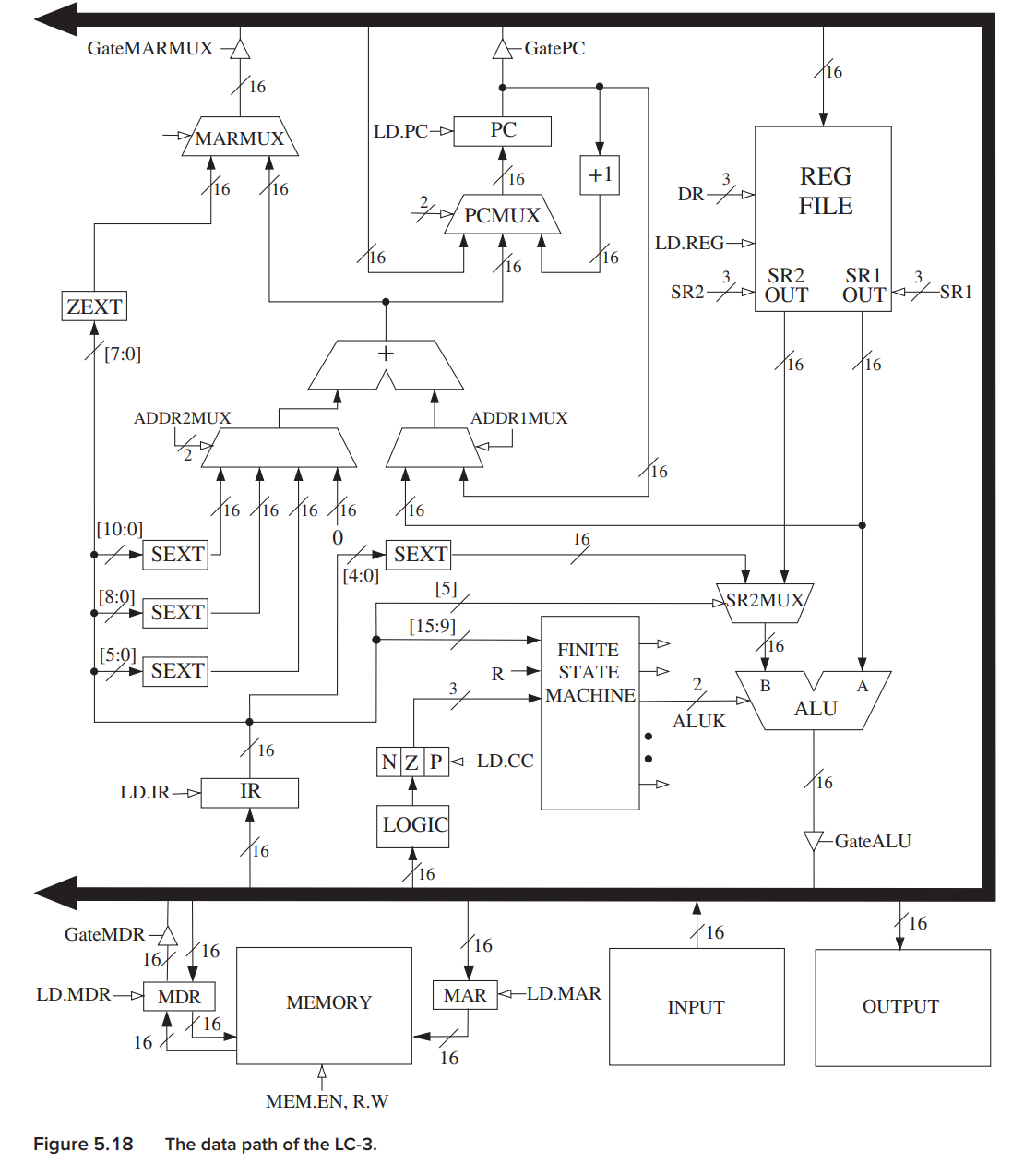
The Global Bus
The heavy black structure with arrowheads at both ends represents the data path's global bus.
- The LC-3 global bus consists of 16 wires to allow one structure to transfer up to 16 bits of information.
- Exactly one value can be transferred on the bus at one time.** So you can see everywhere can transfer value to the global bus has a gate to ensure there is only one value transferred on the global bus.
- The structure wishing to obtain the value being supplied can do by asserting its LD.x(Load Enable) signal.
Note that not all computers have a single global bus.
Memory
Note that there is a MEM.EN,R.W to decide whether the memory is read from or written to.
the ALU and the Register File
Don't forget the value may input to logic to set CC or not.