Clock Tree Synthesis
约 4175 个字 6 行代码 27 张图片 预计阅读时间 14 分钟
Abstract
- Implications of Clocking
- Clock Parameters
- Implications on Timing, Power, Area
- Clock Distribution
- Clock Tree Synthesis in EDA
- Clock Generation
- Clock Domain Crossing
在之前的阶段中,我们都认为时钟是 ideal,现在所有的时序单元都已经放好了,我们要给这些时序单元提供真正的时钟信号,才能让我们的分析变得更加准确。直接用一个时钟作为 Source,连接到所有的时序单元的 Clock 接口,会导致 PPA 不好,因此需要时钟树综合。
Implications of Clocking
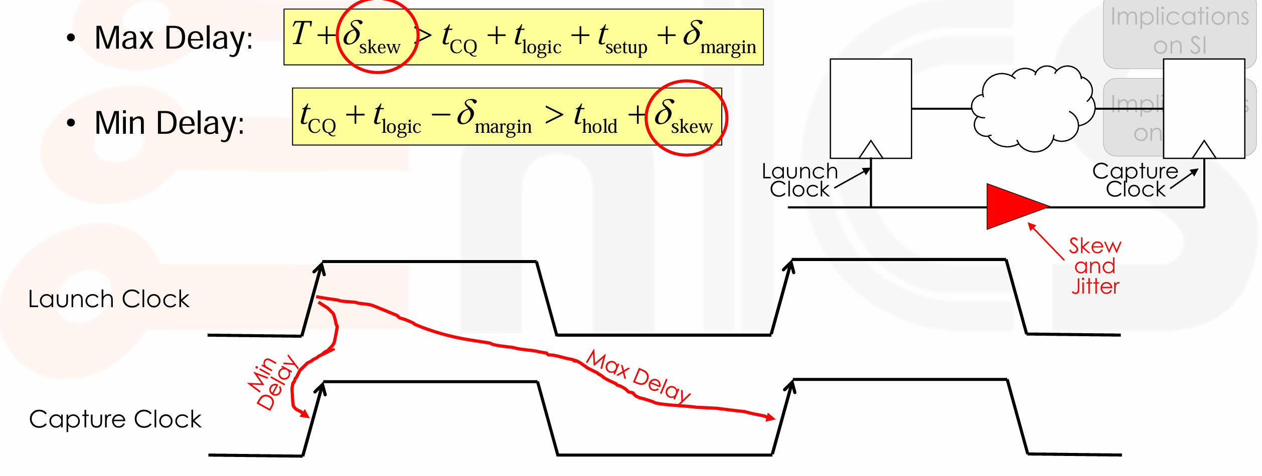
Review timing constraints
Clock Parameters
-
Skew and Jitter
-
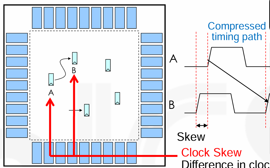
Skew: Difference in clock arrival time at two different registers,反映不同寄存器之间的时钟到达关系。
-
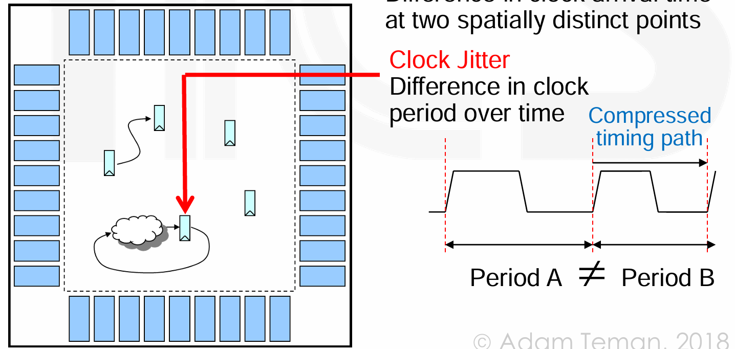
Jitter: Difference in clock period between different cycles,对同一个寄存器。
-
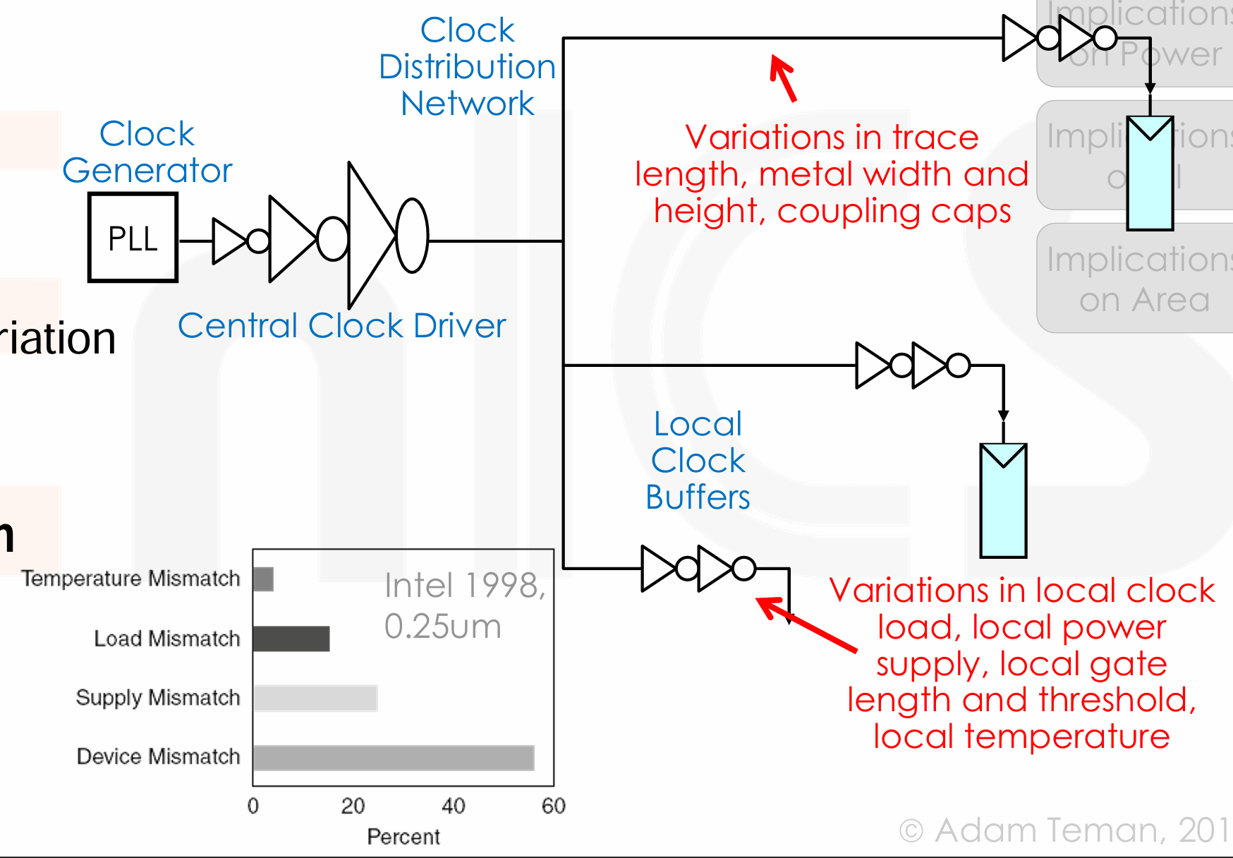
原因:
- Clock Generation,时钟源本身存在不稳定因素。
- Distribution network
- Number of buffers, Device Variation, Wire length and variation, Coupling, Load
- Environment Variation
- Temperature, Power Supply
-
-
Slew: Transition (trise/tfall) of clock signal,时钟信号上升 / 下降也需要时间。
- Insertion Delay: Delay from clock source until registers,指的是 clk 到达寄存器的时间,对于不同寄存器的 skew,可以通过插入不同的 delay 来调整。
Implications on Timing
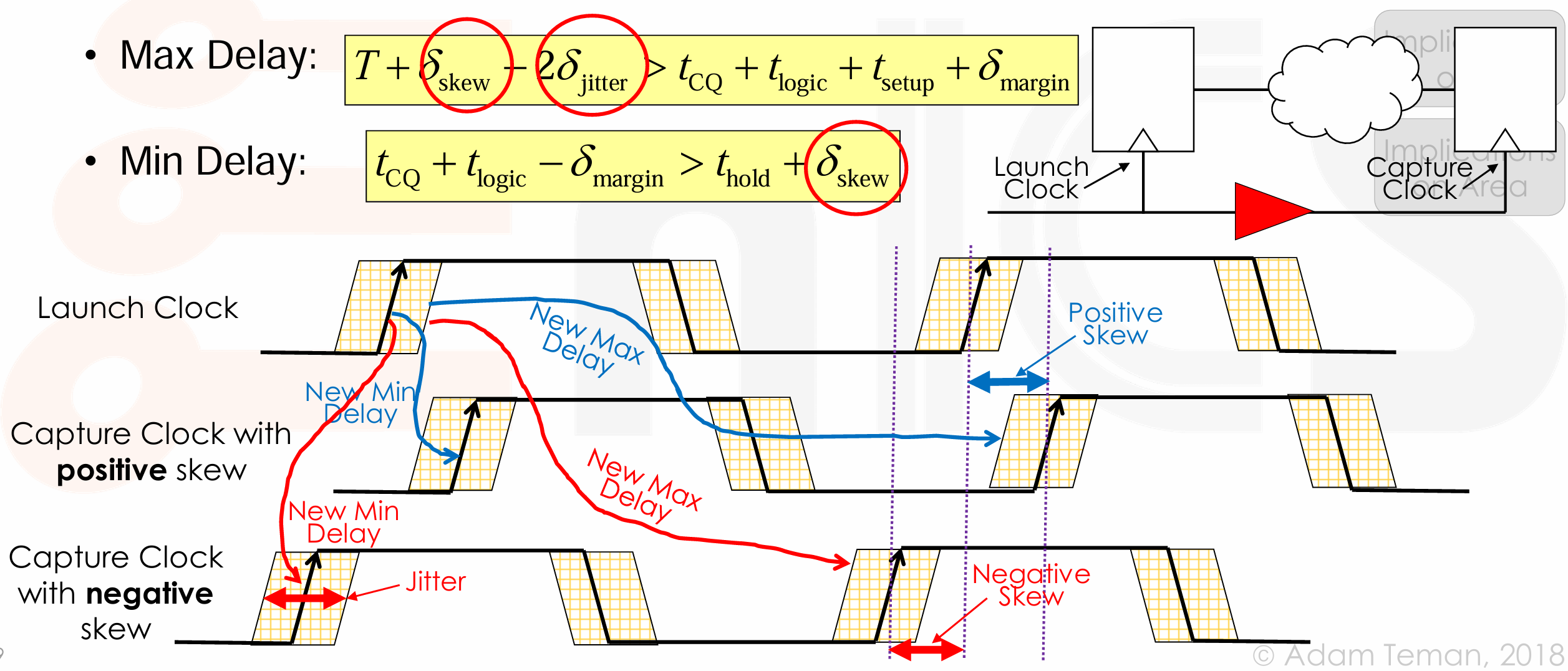
- 对于 max delay,如果 positive skew,看到 > 左边的式子增大,有助于保持不等式成立。这里的 jitter 我们假设最坏情况 launch 时延后,capture 时提前,因此需要在 > 左边减去 2*jitter。
- 对于 min delay,如果 negative skew,看到 > 右边的式子减小,有助于保持不等式成立。
Implications on Power
- dynamic power: \(P_{dyn} = \alpha \cdot C_{eff} \cdot V_{DD}^2 \cdot f, C_{eff} = \alpha \cdot C_{total} = \alpha_{clock} \cdot C_{clock} + \alpha_{others} \cdot C_{others}\).
- 活跃因子 \(\alpha\) 表示设计中实际翻转部分占平均时钟周期。对于 clock network,他的活跃因子是 100%。
- 时钟电容,包括 clock generation, clock elements (buffer, muxes...), clock wires, clock load of sequential elements。
- 因此时钟占据了整个芯片 Power 的很大一部分,考虑功耗的时候需要重点考虑这一部分。
Implications on Signal Integrity
- Signal Integrity is an obvious requirement for the clock network,信号完整性,意味着时钟信号在传输过程中需要保持其原始形状和质量,不受噪声和失真的影响。时钟网络上的噪声可能会导致以下问题:
- Noise on the clock network can cause:
- In the worst case, additional clock edges.
- Lower coupling can still slow down or speed up clock propagation.
- Irregular clock edges can impede register operation.
- Slow clock transitions (slew rate):
- Susceptibility to noise (weak driver)
- Poor register functionality,更差的 \(t_{cq}, t_{setup}, t_{hold}\).
- 需要注意 clock transitions 不是越快越好,这样会导致 overdesign(power area 消耗大
) ,以及对其他信号的干扰增大。一般让 \(t_{rise}, t_{fall}\) 占时钟周期 10-20% 即可。
- Unbalanced drivers lead to increased skew.
- Noise on the clock network can cause:
Implications on Area
- 时钟网络包括时钟生成器、时钟元件和时钟连线,所有这些都会占用芯片面积。
-
此外我们需要考虑布线资源的重要性:
-
Require low RC (for transition and power),为了实现快速和干净的时钟信号过渡,需要低的电阻 - 电容(RC)时间常数。这意味着时钟网络需要高质量的布线资源。
- Benefit of using high, wide metals
-
Need to connect to every clock element (FF),时钟网络需要连接到芯片上的每个时钟元素,这意味着时钟连线需要遍布整个芯片。此外为了从高层次的金属层连接到低层次的金属层,需要使用叠孔,这也会占用额外的面积,并可能增加延迟。
- Distribution all over the chip
- Need Via stack to go down from high metals
-
Clock Distribution
- Routing Problem:
- 只有一个时钟源头,有多个 Sinks。我们需要将他们连接起来。同时让 Clock Skew,Delay,Total wirelength,噪声和耦合效应都尽可能的小。
- Challenge: Synchronize millions (billions) of separate elements,而且时间要求非常严格。总结来说,时钟路由的挑战在于如何在极短的时间内,将时钟信号精确地同步到芯片上每一个角落的元素,同时还要克服信号在传播过程中的延迟和衰减。
- Technology Trends
- Timing,时钟频率越来越高,对 skew 和 transition 的要求随之变高;CMOS 工艺改善使得 PLL 的性能得到改善,减小 jitter;但与此同时其它噪声源可能会增加,比如电源噪声和温度梯度。
- New Interconnect Materials,Copper Interconnect 降低了 RC 时间常数,有助于改善信号过渡和潜在的时钟偏斜。Low-k dielectrics 可以减少时钟功耗,改善延迟、偏斜和过渡率。
- Power,Heavily pipelined design 使用了更多的寄存器,这增加了时钟网络的电容负载;更大的芯片尺寸需要更长的连线来覆盖整个晶圆,增加了时钟网络的复杂性和功耗;随着功能的增加和器件的增多,更多的元素需要时钟信号,这进一步增加了时钟网络的负担。动态逻辑设计中,通常会有更多的元素需要时钟信号,这也会增加时钟网络的复杂性。
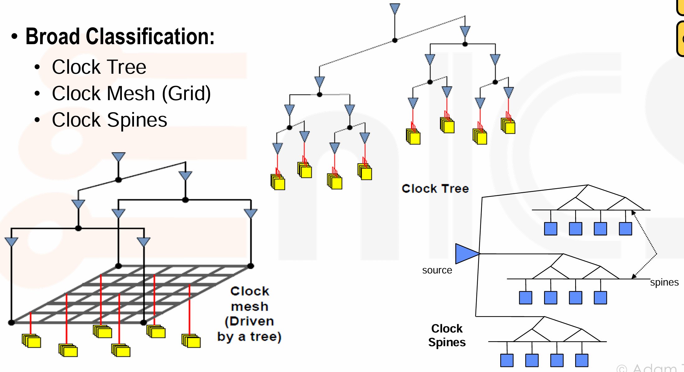
Approaches to Clock Synthesis
-
Clock Tree
- 从单一的时钟源开始,通过一系列的缓冲器(buffers)和驱动器(drivers)将时钟信号分支传递到芯片上的各个触发器。
- Naive approach,对每个 sink 单独布线来平衡 RC-delay,但这种方法会导致功耗过大,且每个网线的较大 RC 值可能会引起信号完整性问题。
-
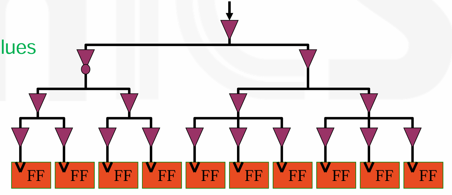
buffered tree:
-
好处是 shorter nets (lower RC),better slew rate (buffers),lower insertion delay, less switching capacitance.
-
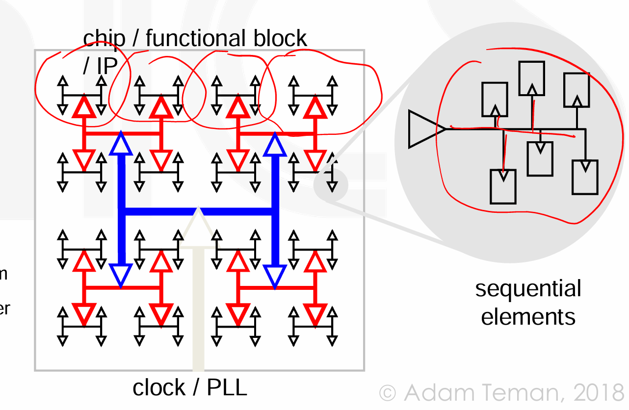
实际的时钟树 H-Tree,他有一个大的中心驱动器,递归的 H 形状结构,在分支点减半连线宽度。
-
这种完美平衡的 H-Tree 在实际应用中很难实现,因此更现实的方法是使用 Tapered H-Tree,其试图实现平衡,但更加灵活,以适应实际设计中触发器不均匀分布的情况。
-
-
standard CTS 方法会考虑到 FF 的实际分布,尝试构建一个平衡的时钟树。在 CTS 过程中,工具会根据触发器的位置和时钟网络的需求来自动放置缓冲器,并调整连线的长度和宽度,以实现最佳的时钟分布。
Industrial H-Tree Examples
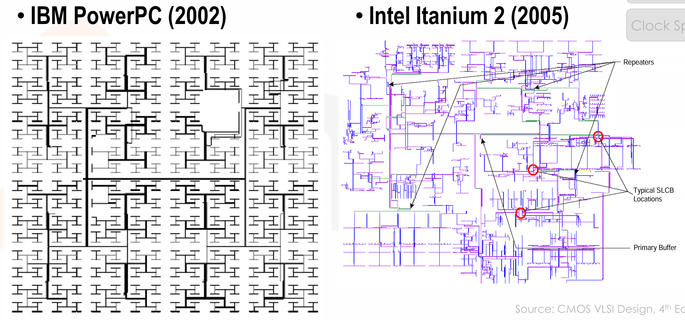
-
Clock Grids
- 时钟网格是一种全局时钟分布网络,它由水平和垂直的时钟线组成,这些线在整个芯片上形成一个网格状结构。
- 好处是 skew 由网格密度决定,而不是特定负载的位置;时钟信号无处不在;对工艺变化的容忍度高;通常能够实现极低的时钟偏斜。
- 但缺点是会带来大量的布线和功耗:连线电容大;需要强大的驱动器;布线面积大。
- Don’t overdesign – let the skew be as large as tolerable,但这样做会导致时钟偏斜变差,从而失去了时钟网格的主要优势。
DEC Alpha –Generations of Grids
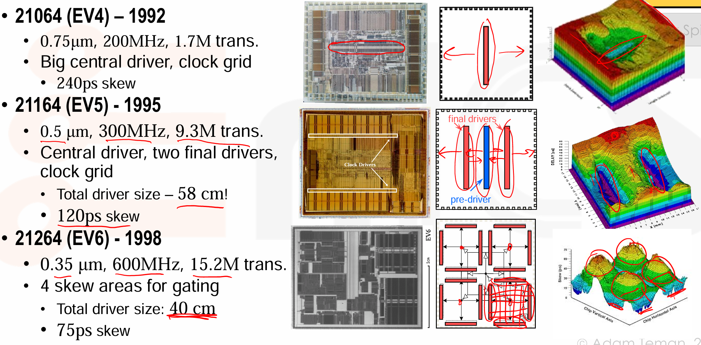
-
Clock Spines
-
介于时钟树和时钟网格之间,对于每个 spine 构建一个 H-Tree,从 spines 辐射出局部的时钟分布。
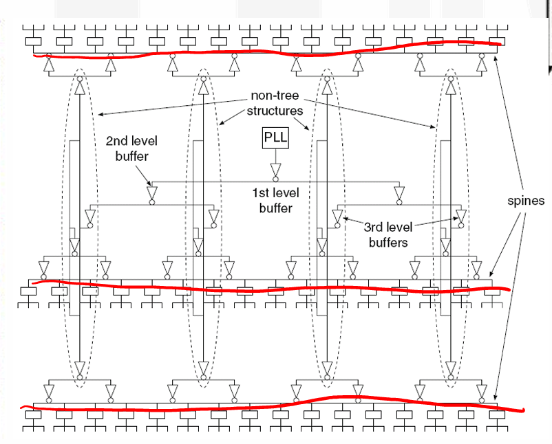
-
Summary of main clock dist. approaches
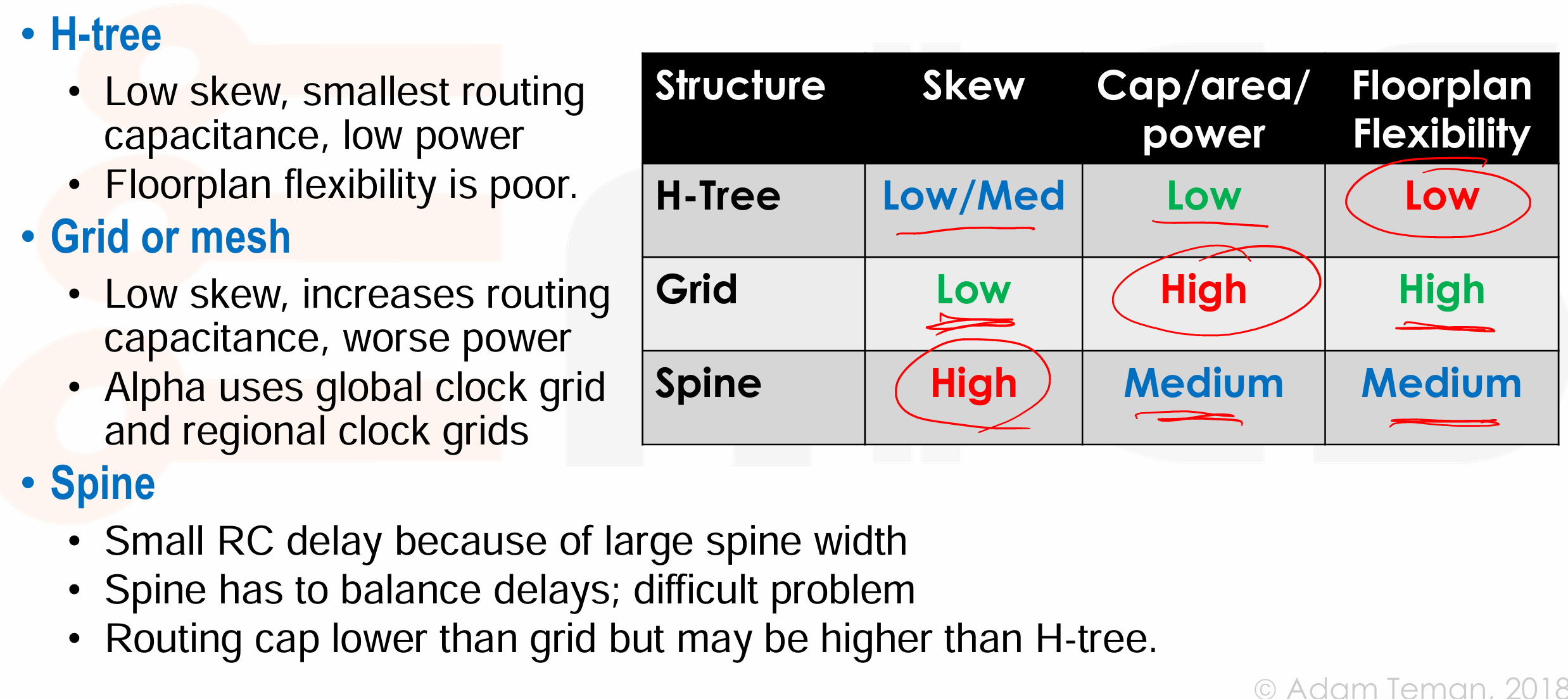
Clock Concurrent Optimization
- CTS 的主要目标,是要满足时序要求和 DRV 约束,minimal skew 不是我们的目标。
- Clock Concurrent Optimization (CCOpt) 提出了一种新的时钟综合方法,它不再将时钟偏斜作为唯一目标,而是同时考虑时序和驱动约束,以及功耗和面积的优化。
- 首先构建一个时钟树,然后检查时序并修复任何违反时序要求的地方(setup and hold
) 。 - 这种方法之所以有效,是因为大多数时序路径都是局部的,它们可能来自同一个时钟分支,因此不需要太多的时钟偏斜平衡。
- 好处是 lower insertion delay, fewer clock buffers, distribution of peak current, a heavy dose of useful skew。
- 首先构建一个时钟树,然后检查时序并修复任何违反时序要求的地方(setup and hold
Clock Tree Synthesis in EDA
- 在 CTS 之前,design is placed. clock pins driven by a single clock source。我们要 buffer clock nets,以满足 DRV 要求,包括设置好的 max fanout,max capacitance,max transition,max length;同时满足时钟目标,包括最小化 skew 和 insertion delay。
CTS Definitions
-
Source: The pin that a clock fans out from,可以是:设计的主要输入端口,例如一个外部时钟信号输入到芯片;一个 IP 核的输出引脚,比如一个 PLL 的输出(PLL 通常用于生成稳定且频率可调的时钟信号
) ;一个门控电路的输出引脚,例如时钟复用器或时钟门控的输出。这些电路用于控制时钟信号的路由和开关。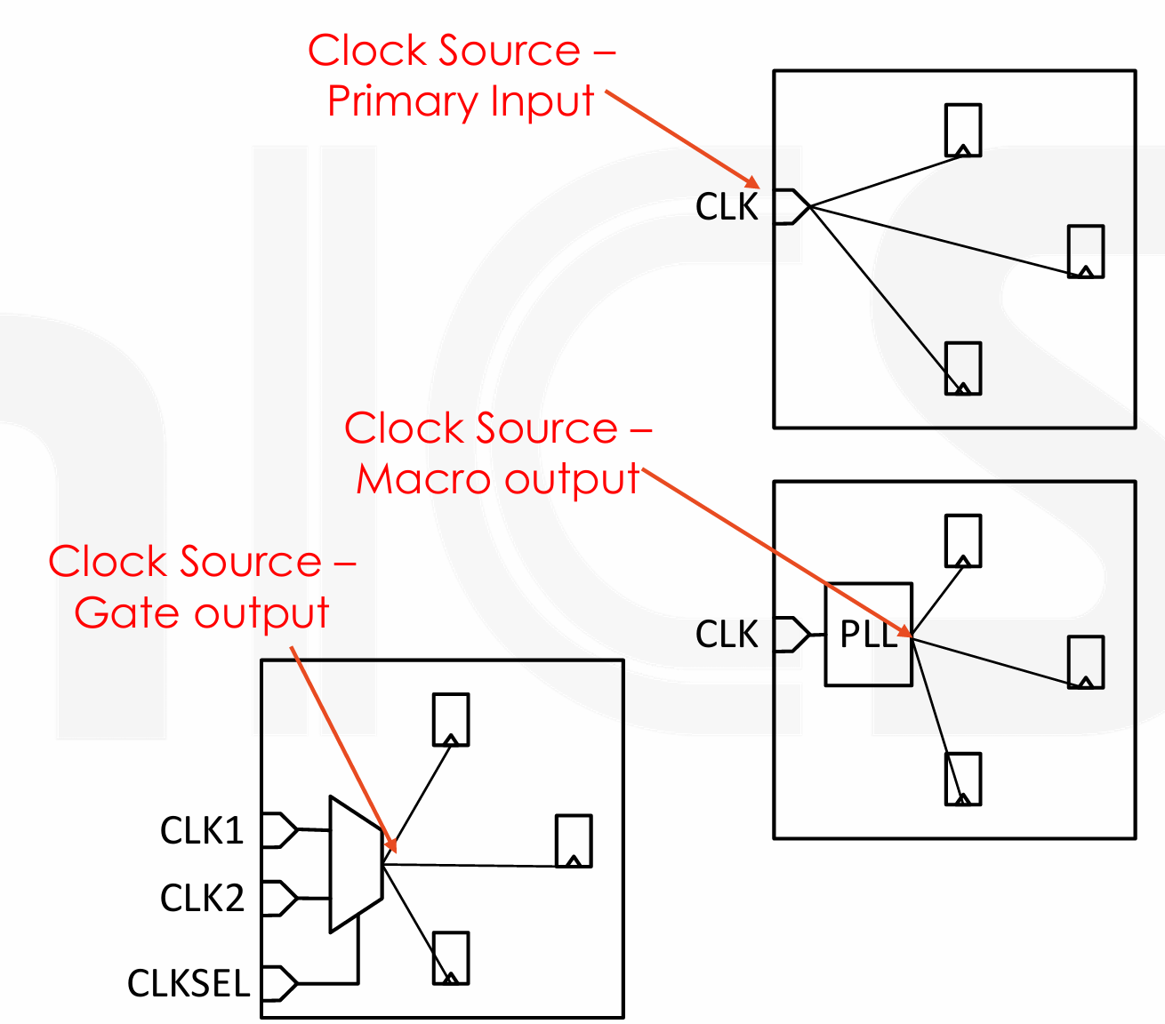
-
Sink: All pins that receive the clock signal,可以是:寄存器(FF, latch)的时钟输入引脚;IP 核的时钟输入引脚(如 SRAM
) ;主要输出端口,比如时钟信号需要从当前模块驱动到外部。 - Trees: The root of a circuit graph for buffering.
-
Skew Groups: A subset of clock sinks to consider for skew balancing/analysis,我们将一部分 Sink 划分为一个 Skew Group,用于分析和控制 Skew。默认情况下,时钟树所有的 Sinks 属于同一个 Skew Group。
-
不同时钟的接收端可以属于同一个时钟偏斜组(例如,时钟和生成的时钟
) ,这意味着它们在时钟树上可能共享相同的路径或缓冲器,甚至一个接收端可以同时属于多个时钟偏斜组。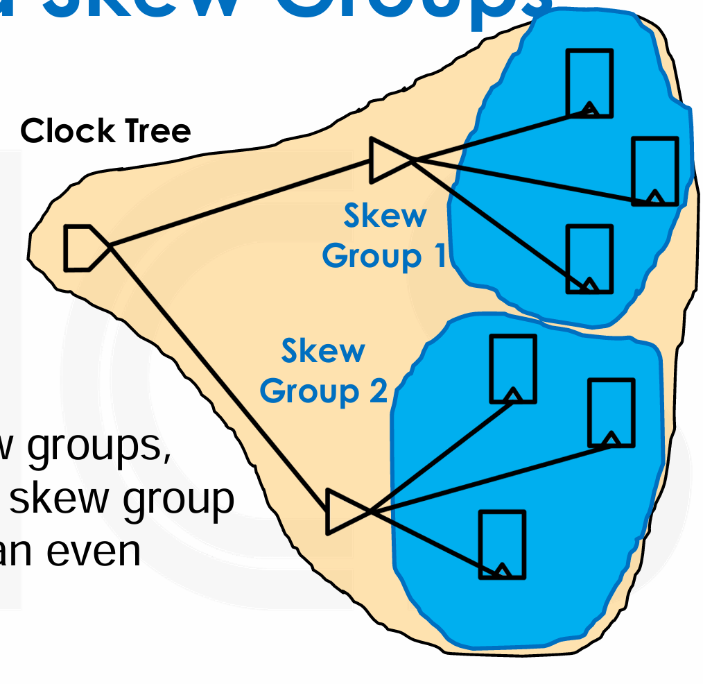
-
Basic CCOpt Commands:
-
-
Pins
-
Stop Pins,时钟树的叶子节点,时钟网络将缓冲到停止引脚,但不会接着往下传递了。
-
All clock sinks are implicit stop pins,即我们不需要显式声明就会将时钟接收端作为停止引脚。
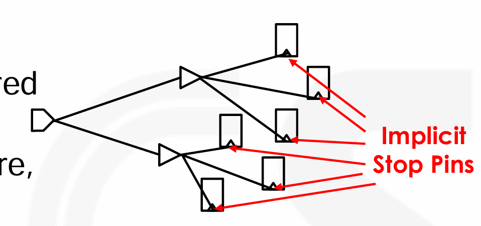
-
我们也可以显式声明,将额外的 pins 作为 stop pin。如
set_db pin:INV1/A .cts_sink_type stop,这里表示希望在 buffer 处就停下,不要传到后续的 sink。- Ignore Pins,本身是时钟网络上的引脚,但它们在任何时钟偏斜组中都不会被视为时钟接收端,因此也就不需要进行时钟偏斜平衡 / 分析。
-
时钟网络将缓冲到忽略引脚,但不会接着往下传递了。
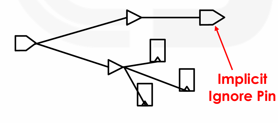
-
可以通过下面的命令声明 ignore pin,如
set_db pin:div_ff1/CK .cts_sink_type ignore.- Exclude Pins,与 Ignore Pins 相似,但时钟网络不会缓冲到 Exclude Pins.
- Through Pins,指那些本来会被视为 Stop pins 的引脚,但我们希望时钟信号能够通过它们传播。
-
Through Pins 允许时钟信号在不被视作最终接收端的情况下通过某些节点。这样做可以保持时钟网络的连续性,同时允许在这些节点上进行缓冲和其他操作。在 Innovus 的新版本中,不再需要显式地定义 Through Pins,而是通过将它们标记为 Ignore Pins 来实现相同的功能。
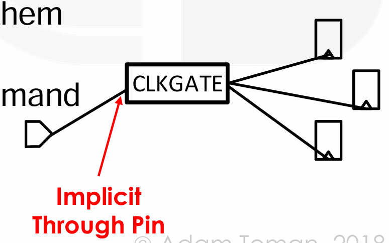
-
-
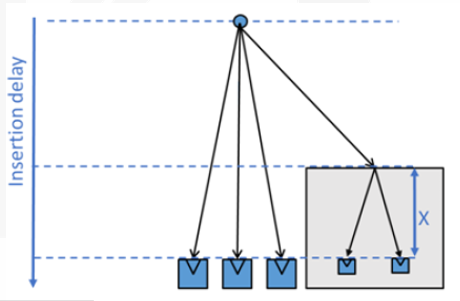
Insertion Delay Pin / Float Pin
-
有些情况我们希望 clock 到达特定 stop pin 的时间比其他 stop pin 早或晚(例如 macro 内部有一定的 insertion delay,那么我们就希望让这个 macro 的 clock 更早到达以平衡 skew
) 。
-
可以通过下面的命令声明 float pin,如
set_dbpin:mem/CK .cts_pin_insertion_delay150ps.
-
Pin Type Summary
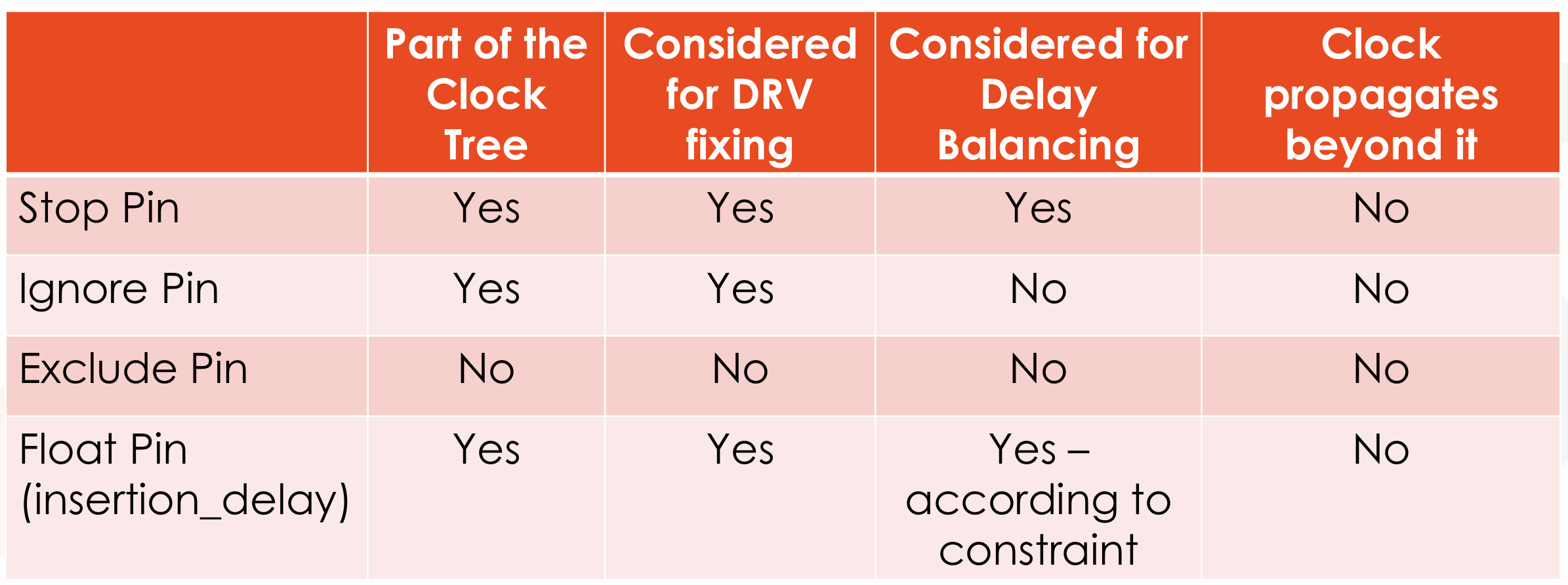
-
Clock Net Routing
- Clock nets are very important in terms of signal integrity.
- 因此,我们通常在在 CTS 阶段会先 pre-route 时钟网络,此外还需要
- 优先选择 routing track,为了减少 RC,我们通常优先选择 higher, thicker metals 来布线时钟网络。高层的金属通常具有较低的电阻,而且与衬底的电容较小,这有助于提高时钟网络的性能。
- Apply shielding to clock nets,通过在时钟网络周围添加保护层或使用专门的屏蔽轨迹,可以减少电磁干扰。
- Consider adding DeCaps next to clock buffers,去耦电容可以用来过滤时钟缓冲器输出端的噪声,通常放置在时钟缓冲器的附近。
-
How do we route clock nets?
- 这些 nets 很特殊,不能用默认规则,要使用 NDRs(Non-Default Rules)。比如 double-width, double-spacing。
- In Innovus, we differentiate between three types of clock nets:
- Top: The initial branch of the clock tree. Very wide and high.
- Trunks: The main branches of the clock tree. Wide and high.
- Leaf: The bottom levels of the clock tree. Closer to the logic.
-
还需要指定 Routing 类型,定义首选的布线层和屏蔽技术。
Shielding and Non-Default Routing Rules
-
首先定义 NDR 规则,比如 Double width、Double Spacing,这个规则的名字叫做
CTS_2W2S。我们定义的规则允许我们指定时钟网络布线的特殊要求,例如更大的线宽、间距或特定的布线层。 -
然后我们创建用于时钟树综合的 routing type,type 名字叫做
cts_trunk。我们可以指定时钟信号应该优先在哪些金属层上布线,以及是否需要采取屏蔽措施来保护时钟信号免受干扰。 -
最后我们上述定义的属性作用在 trunk 类型的网络上。这样,Innovus 就会根据定义的 NDR 和布线类型来布线时钟网络,确保时钟信号的质量和完整性。
- Analyzing Clock Trees
- What the clock root is.
- What the desired clock sinks and clock tree exceptions are.
- Whether the clock tree contains preexisting cells, such as clock gating cells.
- Whether the clock tree converges, either with itself (a convergent clock path) or with another clock tree (an overlapping clock path).
- Whether the clock tree has timing relationships with other clock trees in the design, such as inter-clock skew requirements.
- What the DRV constraints are (maximum fanout, maximum transition time, and maximum capacitance).
- What are the library cells to use for implementing the clock tree.
- What the routing constraints (routing rules and metal layers) are.
- Clock Tree Optimizations
- Clock Tree 优化前后的对比。包括但不限于使用 Gate relocation、Buffer relocation、Buffer Sizing 等技术。
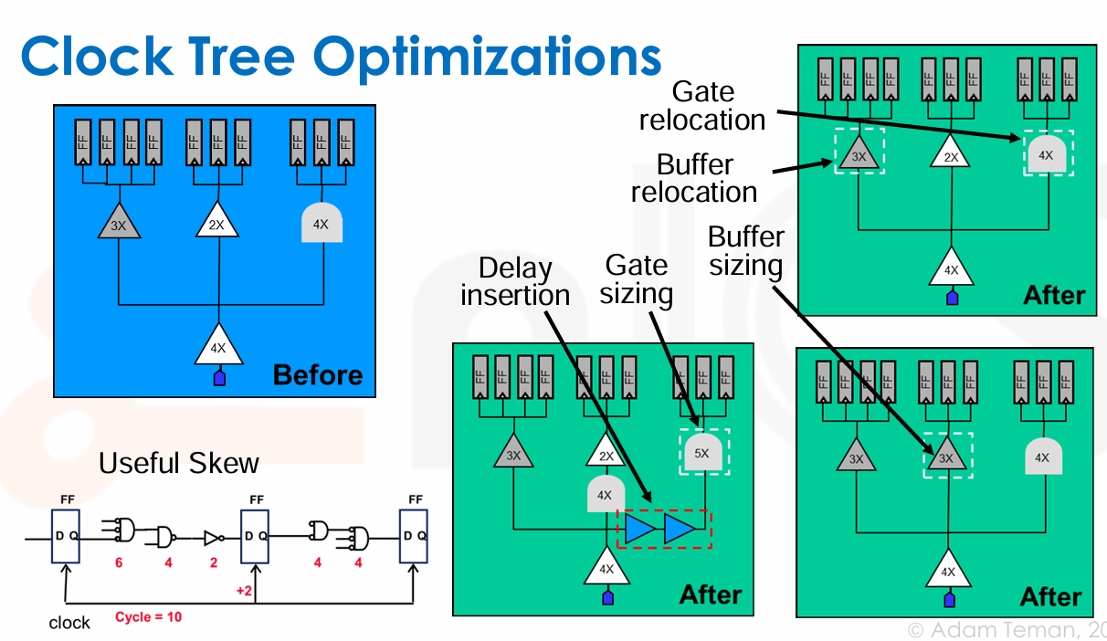
-
-
Post CTS Interface Timing
- 之前我们认为时钟是理想的,现在在 CTS 后 in2reg 引入了 positive skew,reg2out 引入了 negative skew。
- 因此我们可以通过设置 max/min delay,或者在 IO ports 上加上 average insertion delay。
- Reducing Clock Distribution Problems
- Use latch-based design
- Time borrowing helps reduce impact of clock uncertainty
- Timing analysis is more difficult
- Rarely used in fully synthesized ASICs, but sometimes in datapaths of otherwise synthesized ASICs
- Make logical partitioning match physical partitioning
- Limits global communication where skew is usually the worst
- Helps break distribution problem into smaller sub-problems
- Use globally asynchronous, locally synchronous design
- Divides design into synchronous regions which communicate through asynchronous channels
- Requires overhead for inter-domain communication
- Use asynchronous design
- Avoids clocks all together
- Incurs its own forms of control overhead
- Use latch-based design
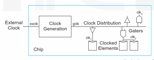
Clock Generation
- 生成时钟最简单的方法就说使用 ring oscillator,即一个环形电路,上面放一些反相器,这样可以得到 0 1 交替的信号。但是这样得到的信号不稳定,易受 PVT 影响。
-
通常是在芯片外部使用专用的 cystal and oscillation circuit 晶振电路产生时钟。
- 这个片外时钟只有一个,并且时钟频率很受限(最大 100MHz)
- 我们就需要使用片上的专用时钟生成器,通常是 PLL/DLL。
-
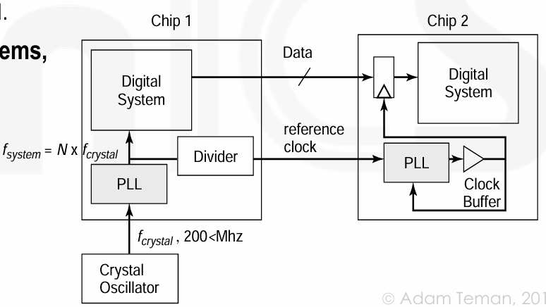
Local Clock Generation
- 外部时钟的问题:频率受限;无法控制 clock phase 相位,因此和外部时钟域的通信是不同步的。
-
因此可以使用 Phase-Locked Loop (PLL) 锁相环,或者当不需要对时钟倍增时,可以使用 delay-locked loop (DLL)。
-
PLL 工作方式:检相器(PD
) 、环路滤波器(LF)和压控振荡器(VCO) 。作为一个负反馈系统,在反馈回路中 VCO 的输出被分频器分频到低频后,通过检相器和参考时钟比较产生相位差信号,接着该相差信号在前向通路上,被电荷泵和环路滤波器处理后产生电压控制信号,从而反过来控制 VCO 的输出。
Clock Domain Crossing
-
Asynchronous clocks cannot communicate with each other in a straightforward fashion.
-
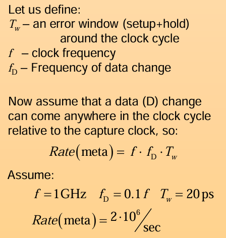
Metastability: 亚稳态是指一个触发器(flip-flop)的输出在稳定的高电平或低电平状态之间的一种不稳定状态。当异步信号在触发器的建立时间(setup time)和保持时间(hold time)窗口内发生变化时,就可能会出现亚稳态。他可能带来如下问题:
- High propagation delay at the fanout.
- High current flow in the chip (even burnout).
- Different values of the signal at different parts of the fanout.
What is the probability of metastability?
-
Data Loss: 数据丢失可能发生在源端产生新数据时,而目的端尚未捕获前一个数据。
- Data Incoherency: 数据被延迟捕获,导致多个相关信号处于不同的状态。
- Solutions: Synchronizers
-
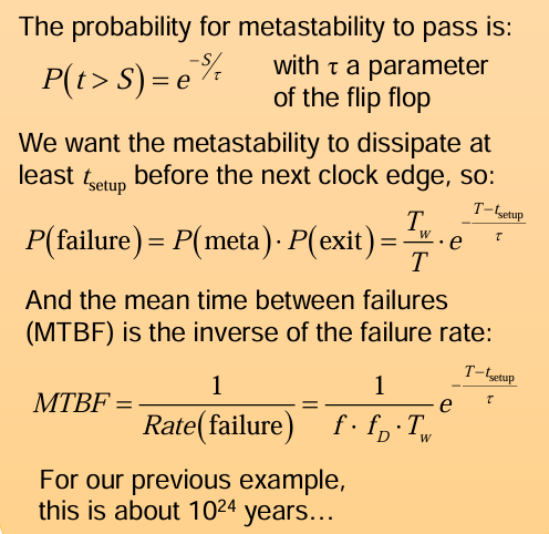
cascading two or more flip flops,将两个 FF 串在一起,这样 signal 有了更多的一个周期来稳定数据。

-
注意的是,这里有可能一个 cycle 内无法处理好信号。
What is the probability of failure?
-
注意同步器只能解决亚稳态,没有解决数据丢失问题和数据不一致问题。
- To eliminate data loss:
- Slow to fast clock – we won’t lose any data.
- Fast to slow clock – hold source data for several cycles.
- for data coherence, we need more thinking:
-
Handshake protocols.
-
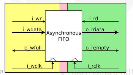
First-in First-out (FIFO) interfaces
- Other solutions (Gray code, Multiplexers, etc.)
-